Thursday, January 29, 2015

Reassembly Panic!!

AAAAGGGHHH!!!

Despite my stern admonitions to DOCUMENT EVERYTHING, I FAILED UTTERLY to record how this horrific stack of iron goes together before I dismantled it!!

Trying to put it all back together was like trying to herd cats!  All the plates are layered, lapped, bent, arched, butted together.  Everything is on different planes - there was no laying everything down FLAT to reassemble!

And all I had to go by, to reassemble everything, was one lousy picture of the buggy the day I brought it home!

What was I thinking!!!

Anyway, as you can see, I have remedied that problem, so that now, after a break to catch up on my OTHER life, I'll be able to attack the left side spring with confidence!

 So, after a week or so of frenzied work, I have stripped, de-rusted, surfaced, primed and reassembled the right side spring.  I've attached the wooden bolsters to make sure of spacing and also to stabilize things.  They'll be taken off and painted separately.  None of the bolts are tight, as there is bound to be a lot of grunting and pushing and pulling to reattach this assembly to the axles!

So these are just some pictures of progress. Amazingly, there was very little 'reassembly rash' to sand and re-prime.

This picture is looking from back to front.


Front to back.


Step also bolts to the cross bar under the bolster.


The first time I saw the carriage I thought I had some broken spring plates.  The little crack is actually where the ends of the crossbars come together.


Just like new!  :o)  Sound and solid for another hundred years of driving pleasure!!

Sunday, January 25, 2015

Identifying Parts


Caution:  Boring content ahead.

I'm sure that a lot of people have found out the hard way, that it's not a real good idea to dismantle a carriage, thinking they will remember how to put it back together without having created a detailed road map as they went along.

Digital cameras make it easy for us to photo-document various assemblies and parts, but when it comes down to re-assembling a pile of iron into a useable carriage, it quickly becomes apparent that lots of these parts look the same, but don't fit where you're trying to put them.

Unless you've given each part an identity, and recorded its identity in print somewhere.

You not only need to know where the part came from, but how it was oriented; what end of the small parts above faced forward?  Which part went on the right side?  Which part went on the left side?

Carriage parts were largely hand made, hand fitted, hand drilled, hand threaded, hand bent.  That means that...especially before castings became widely available, hand made parts fit one place on the carriage, and one place only.

And putting one of those curved parts on backward, means you're going to have to pull it back off and put it back on again, and in the process, tear up any of the surfacing you've done to the parts they're holding together!

 Take, for instance, these hand made iron mounts for the dashboard.  How many differences can you find?  The top hole is round on the left part, square on the right part.  The top edge of the right hand part is more rounded than the left.  The bolt and screw holes are probably not identically placed, meaning the matching holes in the carriage body will be drilled for one of these pieces but not the other.


Look at the asymmetrical curve of this "saddle clip" (yes, it's broken and must be replaced or repaired).  When these things are first made, they are flat, then bent to the shape required for the job.

BTW, in my frustration at having twisted the threaded stud off this part, I forgot to mark it!  I am only modestly certain of where it goes, but have no idea what its orientation is!

Now...Which side goes forward?  Which side faces rearward?  How are you going to know a month from now, when you want to put everything back together!

Springs are sometimes asymmetrical and when the leaves are all separated, you need to get them re-aligned correctly.  How will you do that unless you know which is right hand, which is left hand, and which direction each leaf is supposed to face?

Yes, you need a marking system, and even the most insignificant-seeming part needs to be identified as to its position on the carriage, and its orientation.

When I dismantled this running gear, I used masking tape and a marking pen, but that all has to come off for the cleaning process.  So how do you mark parts?  You can use a series of punches, maybe stamping with a number, anything, so long as it will withstand the most destructive cleaning process you plan to use, such as sand blasting, grinding, paint stripping or wire wheel.


You'll have to devise your own system.  For the longitudinal (facing forward and backward, as opposed to side to side) springs, I am marking individual spring leaves on the underside, FORWARD of the central hole.  One mark for right hand side, two marks for left hand side.  This mark was made with a Dremel tool and a steel burr.

You may recall from a previous post, that I moved two leaves from each spring to opposite sides of the carriage.  Those re-positioned leaves have a mark designating the side of the carriage on which they are now positioned.  This is one of very few times that I would ever reposition parts on a carriage.  The other items I repositioned on this carriage are the rub rollers, to take advantage of the undamaged ends of the rollers without having to replace them.


 This little plate supports the front end of a main spring leaf.  There are four such support plates.  It is essential to know where this one goes because...


It is mated to this saddle clip, and to the holes in the front end of the spring.  There are two holes drilled in the end of the spring leaf.  This clip must pass over the spring bar, through the holes in the spring leaf, then through the holes in the above plate.  The holes in THAT end of THAT spring leaf are probably spaced a little differently than any other pair of holes on the carriage.


This is what the bottom side of the four spring end support plates look like.  All alike; all slightly different.


The seemingly identical RIGHT REAR spring end support plate also has two marks, but they are oriented differently.


The above piece mates with a steel spring block, which is drilled to fit the axle.


Other view of the spring block.


And this clip holds the SPRING end (not the REACH end) to the rear axle.

The stacking arrangement (for my information) is: Clip, axle cap, axle, spring block, spring, spring end support plate, bolts.


It is also critical to document the location of individual BOLTS and their respective nuts.  Many individual pieces may be stacked together, all hand-drilled (with a hand cranked brace no doubt, or perhaps a punch of some sort), slightly out of alignment.  Oh, have I ever experienced this!  The bolts holding these parts together are commonly bent especially to snake through these multiple, slightly offset holes.  If you value your sanity, you will record where every bolt fits onto the carriage!  To do this, I just punch holes in a piece of cardboard, run the bolt into it, screw on the nut on the underside, and write the details on the cardboard.

UPDATE!

  The usefulness of the bolt board has been greatly enhanced by using it to identify small parts!


It is extremely difficult for my illogical brain to put together a logical marking system for these parts.  Even as I wrote this, I had to dash out to the shop to look at the still-assembled left side springs to double check my notations.

Anyway, you get the idea.  I'll be using this blog post to catalog all the other small parts as I continue to disassemble the running gear.  That will be for my benefit at reassembly time, but you're always welcome to come back and look.


Thursday, January 22, 2015

"Surface Conditioning" Metal

Here is the first group of small parts from the running gear that have been cleaned.

The process was:
  • Wire wheel (bench grinder and angle grinder) all the paint and dirt away
  • Electrolytic De-Rusting
  • Two coats of SEM Rust Mort to kill the flash rust and protect the parts until they are ready for further treatment.
At this point, a restorer has to decide just how much an excellent paint job means to them.  These parts could be painted as is, or receive further treatment that will ensure the best paint job I can manage when the time comes.  All these parts are highly visible and may be considered ornamental as well as functional.  As a matter of fact, I intend to draw a certain amount of attention to them in the future paint scheme.  So it means a lot to me to have them ready to receive my best effort at painting.

Despite the fact that this carriage has actually been very little damaged by heavy rust, this macro shows that the surface of the metal is very rough.  I suspect it is a sand casting.

This roughness is not something that "paints out".  It will still be there after the last coat of paint is applied.

Unless I do something about it now.


3M makes a nifty product called "Scotch Brite Surface Conditioning Disc".

These discs "Velcro" onto a drill- or angle grinder-mounted pad, and they are used for smoothing surfaces.  Like sandpaper, they come in coarse, medium and fine.

Since I don't need aggressive scale removal or anything, I am just going to polish these surfaces up a bit with a fine disc.


The bottom part has been given a little polish-up.

These plates sit atop the springs and they're made to be pretty as well as functional.

Unlike automobiles, every bit of the running gear on a horse drawn vehicle is visible and forms a significant component of the visual pleasure of looking at the vehicle, if well treated.

No point putting these pretty things back on, painting, and then saying..."Well...THOSE are ugly!"

That's what poor surface preparation gets you.


There are no deep pits on the surface that would require a product like automotive body filler to fill.

Instead, I'm going to apply a very thin coat of automotive "spot putty", also called glazing compound.  This compound dries for sanding in about 15 minutes IF IT IS APPLIED VERY THIN.

Products seem to be changing all the time.  A spot putty that I used and really liked about four years ago is no longer being made.  This stuff seems to work pretty well.

Note that I have also treated the bolt head.  Anything that's visible (except maybe the nuts, which are in excellent condition) will be surfaced.


Once the spot putty is dry, I sanded the majority of it off with 220 grit dry, finishing up with 400 grit dry.

A wipe with degreaser and a tack rag, then a quick spray with Rustoleum rattle-can primer, and this part is ready to be carefully stored away in anticipation of re-assembly.


By the way, these two small marks, made with a Dremel tool and a burr, tell me that THIS part goes on the left spring, and THIS end of the part faces forward.

The right hand part has ONE mark on the forward-facing end of the part.

Also note the roughness of the un-conditioned underside of the part.

My next post should have the results of my visit with the blacksmith about those worn and broken bolts.  In the meantime, every visible surface of every piece of the running gear will receive the same surface conditioning treatment as this part has undergone.  That should keep me off the streets for awhile!

Wednesday, January 21, 2015

Springs and Other Hardware Trivia

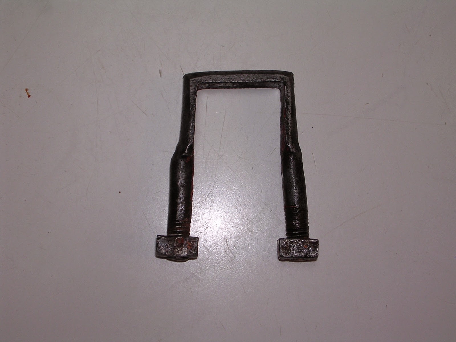
Remember this little fellow from the last post?  He's got one 3/8" threaded stud and one 5/16" threaded stud.

Why?


Because he was made that way!

With few exceptions, the hardware on this carriage is all hand forged.  Cleaning the crud off these hand forged clips revealed no damage (to either clip made like this).  One stud is just a little thicker than the other one, and they were threaded accordingly.

If the blacksmith was good enough to hide any evidence of a repair, I don't think he'd let this inconsistency slip past him!

The secret life of carriages!


Metal Cleaning Begins


There are many ways to clean metal, with sandblasting probably being the most popular choice.

I don't use sand blasting for my own reasons.

I don't have a sand blaster.

I'm not fond of sending rare, carefully cataloged and grouped parts out to indifferent shops.

If you send the whole lot out for sand blasting, you immediately have the worry of re-rusting, and having to deal with a hundred pounds or more of rusting iron in a very short period of time is stressful.

So basically, I rely on elbow grease and practically free electrolytic derusting.  Electrolytic derusting can be easily done in small batches, and cannot over-clean the metal.  You can leave the parts processing in the solution until you're actually ready to do something with them.

One of the drawbacks is that you have to take the dirt and paint off first.  The other major drawback is that the parts will flash-rust almost as soon as you take them out of the solution.  Even though I oven-dried my first batch of parts, they quickly produced a film of light rust, and so the next step was to coat them lightly with a quality rust converter such as SEM Rust-Mort.  This will hold them nicely until ready to surface them.  Body fillers can be used over Rust-Mort.

Important update:  After drying the parts with a rag, wiping them down with acetone seems to postpone flash-rusting.  

Several small parts are presently hanging with a couple coats of Rust-Mort to dry overnight.

Rub Rollers

For those new to antique carriages, an explanation.

In days gone by, many thousands of buggies were produced in such a way that in a turn, the tire on the wheel would contact the carriage body.  This could result either in body damage from the iron tire or worse, the tire could jam against the body with the disastrous result of having the buggy tip over!

In the case of iron-tired buggies, a "rub iron" projected out from the body in such a way that the iron tire would contact it, allowing the wheel to keep turning, and preventing damage to the body.

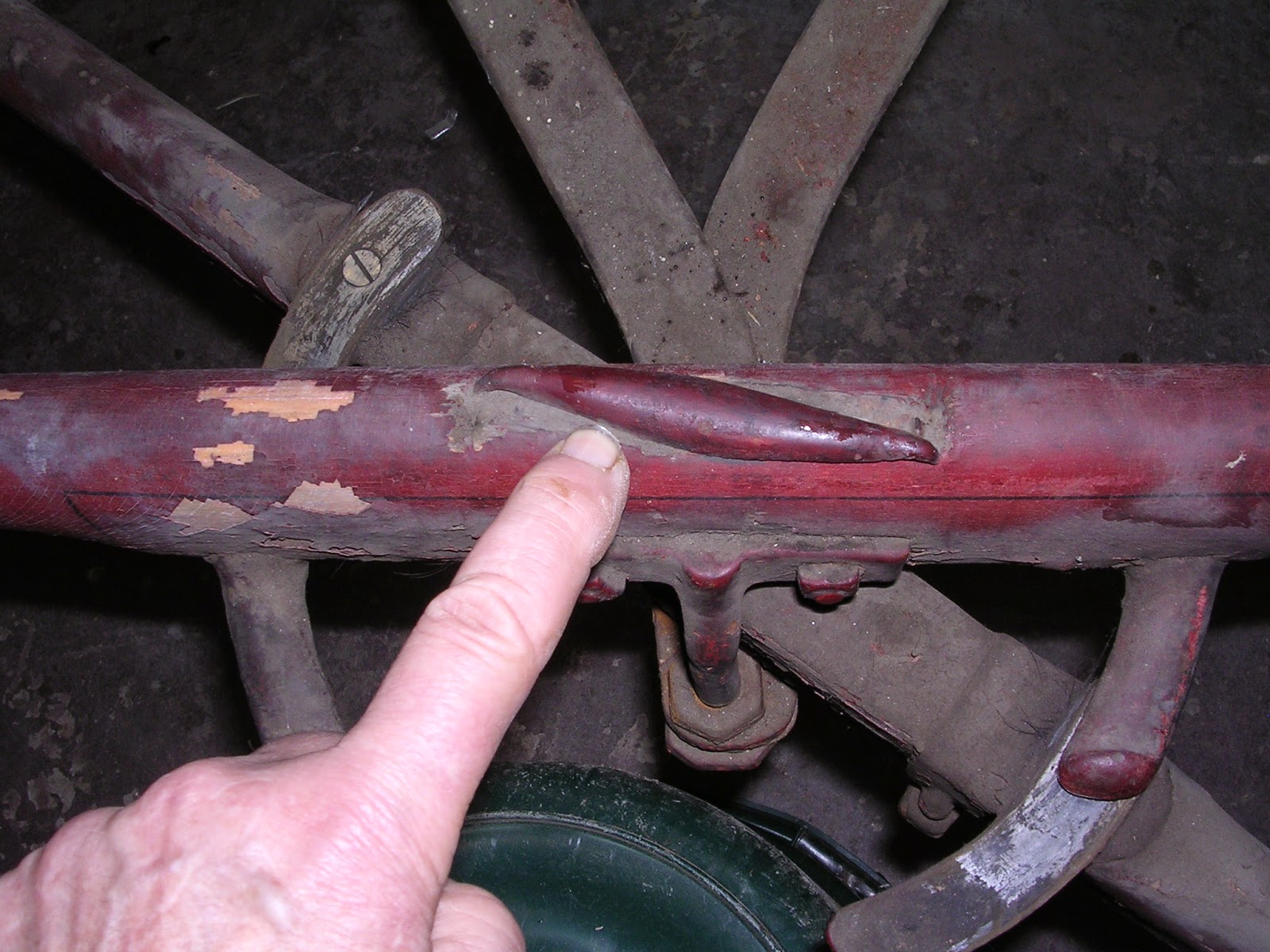
In the case of buggies equipped with hard rubber tires, the rub iron was not adequate.  So the "rub roller" was invented.  The above photo is one of the rub rollers on the project buggy, which has always had rubber tired wheels.  That long slim bar is supposed to roll when the wheel hits it, so that the rubber will not bind, nor be sliced up.

Only you can tell from the wear on these rollers that they ceased to function properly a long, LONG time before the buggy was taken out of service.

New rub rollers are available from Amish shops, but the problem here is, the old mounting plates are curved to fit the underside of the springs, with special built in "stops" as opposed to mounting with two bolts on the flat underside of a buggy body.

My plan was to remove the roller and its shaft and replace them...until I cleaned the paint and crud off and put one of the plates in a vise, grasped the roller with pliers and...with very little effort...turned the roller!  A little WD 40 had them spinning with ease, but with no looseness.

So NOW, the cunning plan is to simply put them on opposite sides of the carriage so that the rubber tires will contact the undamaged surfaces of the rollers.

AND keep them lubricated, and not painted in place.

Springs

This is one full set of side springs, minus the leaves that join the front and rear axles.

Way back when I discovered that one body bolster was 1/2" shorter than the other, my friend and fellow carriage enthusiast, Kathy Ashford, pointed out that the right spring might be sagging owing to the driver always sitting on that side, and that one bolster was cut down in order to even the seat from side to side.

Something I hadn't thought of, despite being familiar with the phenomenon!

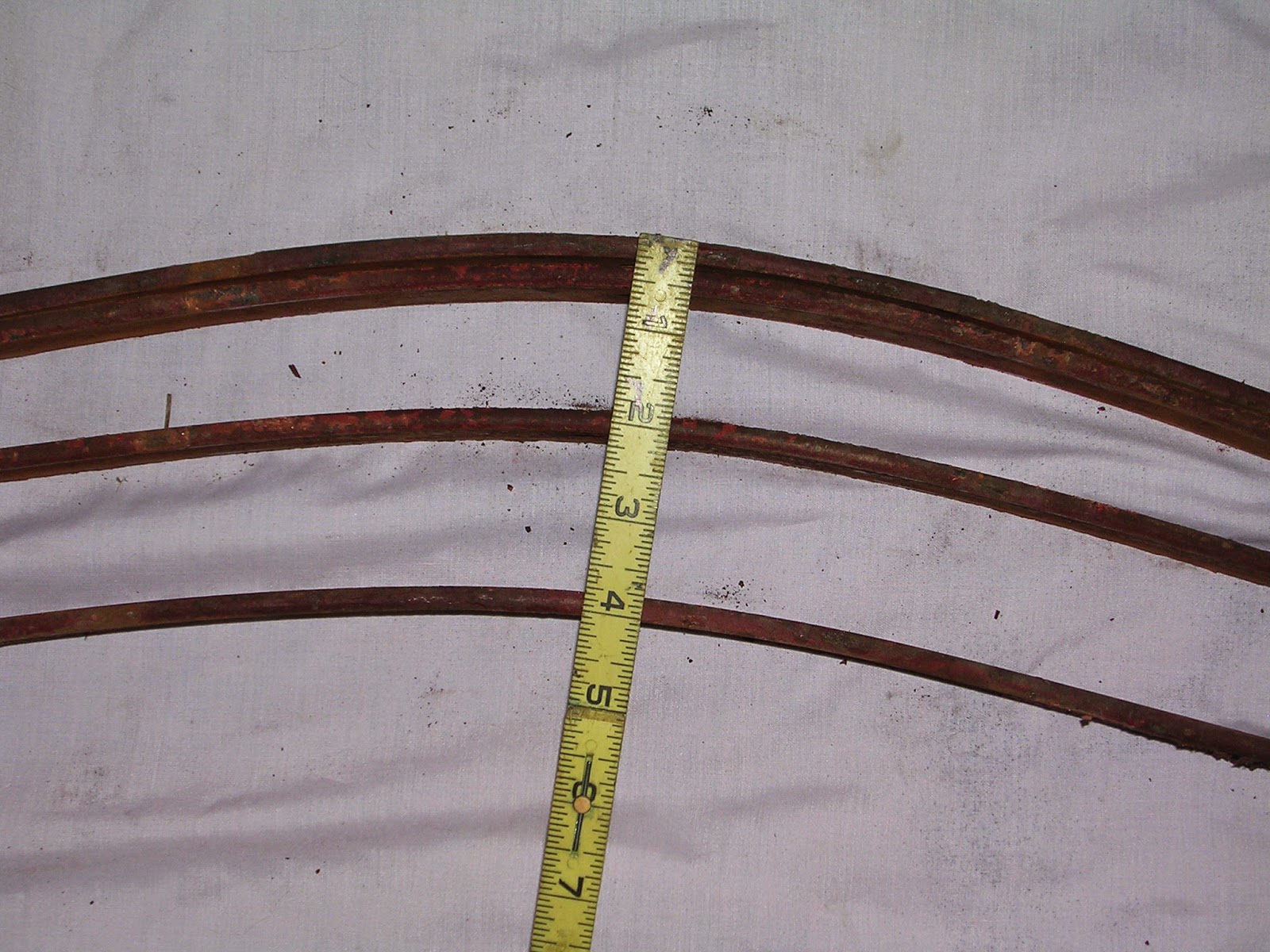
When the running gear was leveled up on saw horses, the distance from the bottom of both springs to the floor was identical.

However when the springs were un-compressed, the space between the highest point of the arch on the right hand spring was 1/2" less than on the left side.  At least some of the spring leaves on the right hand side have sagged.

Fortunately, another carriage enthusiast and friend, Roger Murray, was on hand with a brilliant suggestion...why not swap a few of the leaves from side to side to see if the arches can be evened up?

This I did, swapping the two center plates from side to side.  The result is that the un-compressed space between the spring leaves on both sides is the same; 4".

Now, a little bit more about springs.

The Carriage Museum of America has kindly granted me permission to quote excerpts from their out-of-print book, "Conservation and Restoration of Horse-Drawn Vehicles".  So I will validate my decision to take this easy course of action instead of sending the springs out.

My first reason needs no explanation.  These are not common springs.  To break a leaf would be disastrous, and I want to take no unnecessary chances.  The rest of this information comes to us courtesy of the CMA.

Antique spring steel has an unknown quantity of carbon in it.  Incorrect tempering of steel of unknown carbon content may produce a spring that is too brittle or too ductile.

Modern spring makers, accustomed to working with modern alloys, can run into all sorts of problems when they suddenly switch to antique springs.

Springs do not lose their "temper" unless subjected to temperatures in excess of approximately 600 degrees.  In order to insure  the maximum performance of the steel, the heat treater has to deal with a very narrow margin of error in the final hardening process.

If the steel is too soft, it will not take the stress of bending and flexing.

If the steel is too hard, it will form stress cracks and eventually break.

If the spring is flexed past its maximum point of flexibility, it will move the grain structure of the steel and cause fatigue.  This is probably the number one cause of fatigue.  Usually the springs can be re-arched but this will not solve the problem if the same load is put back on.

There is an ideal height of arch for a spring which will cause the spring to bottom out before it reaches the over-stressed point.  Over arched springs can easily be overloaded, causing them to exceed the maximum flex point.  Under arched springs will bottom out before you get the full benefit from the spring.

These notes were provided for the book by Wana Coach and Company.

In light of the above information, and taking into account the many unknowns about the carbon content, original tempering, ideal arch, etc., it seems I neither want to re-temper, nor re-arch the springs.  The most satisfactory route over all would be to have new ones made, but I wouldn't begin to have a clue where to have that done, nor do I believe it's necessary, given my plans for the carriage's future service.

The middle-of-the-road approach of swapping the leaves from one side to the other seems to be the ideal approach for now.

Monday, January 19, 2015

Breaking Down the Gear

This is where record keeping REALLY becomes important. There are buckets of bolts, screws and small parts on the gear that have to go right back in the exact position they came apart...front, back, right left.  Usually the maker had a marking system consisting of punches in the steel, but that is mostly on major components, not the little bits.

Now the REAL reason for this blog comes out...it's my record keeping system!  I will use it to document every move I make now, so some of it will get boring (I know, MOST of it is boring...)

It's time to begin breaking the gear down into its major components; axles, springs, spring bar.  EVERYTHING will be dismantled.

The Front Axle 

The first thing to do is clamp the ends of the spring leaves together where they meet at the front axle, so things don't go SPROING when bolts are undone!


In order to separate the front axle from the rest of the gear, I first had to release the spring bar, the top tier of the front axle assembly, from the springs.

The "clip"shown bolts through the end of the spring, so these clips are undone first.


Next off is the "king bolt"upon which the axle pivots. The bolt has a "tee" head. It passes through the spring bar, the 5th wheel assembly,the axle, and the ends of the springs (Y shaped assembly at top of photo).


Out with it.


Next is this piece of hardware. It's bolted to the front of the spring bar, passes in FRONT of the axle, then joins the ends of the springs


The bottom nut is removed, while the rest of the piece remains attached to the spring bar for now.

The spring bar is lifted off the axle, and the front axle is removed and set aside for now.


Unfortunately, close examination determined that the two king bolts are too worn to reuse. I have an album of close-ups of these bolts on Photobucket, if you care to see what a "too worn out bolt" looks like.  I will take the axle assembly to a blacksmith and ask him to reproduce the worn parts.

A wise person also pointed out to me that embrittlement - which has already reared its ugly head in this restoration - might be more of a safety risk than simple wear.


The disassembly of the relatively complex front axle will have to wait for new parts. Not like there aren't other things to do!


The Rear Axle

 Dismounting the rear axle wasn't nearly as complicated, but also produced a hardware failure...


The threaded stud on one side of this "saddle clip" twisted off when I tried unscrewing the nut.  The sheared ends show some rust, so I think it had a flaw in it originally.  This "saddle clip" holds one of the springs to the axle!


Total Commitment...

Several wise and wonderful people responded to my request for opinions on how best to deal with the worn king bolts and the final decision is to have them restored or replicated by a skilled blacksmith.

The clip with the broken thread will also go to the blacksmith, because this "saddle clip", a wider version of the axle clip, does not seem to be available new.


No more messing around...this is it. The entire running gear, less axles.  The bottom of the picture is the front of the gear.

While the springs measured the exact same distance from the center bolt to the floor, yes, it's true, you can see that the right side spring (the one on the left of the picture) has lost some of its arch.  I'll talk about that in another post.


Labels, labels and more labels.  Until I actually begin stripping parts and marking them permanently, everything is tagged.

For those of you new to antique carriages, you need to know that the axle nut, the nut that holds the wheel on, ALWAYS tightens when the carriage rolls forward, and LOOSENS when the carriage is pushed backward.  For that reason, the nuts on the left side of the axle screw on counter clockwise.  So even though the axle looks the same from end to end, you do NOT want to put it back on backwards!

I have a wagon I bought at auction, that had had its axle stubs replaced.  The front axle was actually re-installed BACKWARD! I fought the right hand nut for an hour trying to get it to break free so I could take the wheel off.  Finally, in exasperation, I thought, "Oh no..."  I turned the wrench clockwise and the nut came right off...  Yes, the axle was entirely dismantled and put back together correctly.


Anyway, the age of digital cameras and blogging makes it easy to photo-document EVERY detail and record one's experiences as they occur.  This has proven invaluable to me when I go looking for information from a previous project, and is also critical to putting everything back the way it was.

Anyway, here, I'm preparing to disassemble the left spring, which is the only way to get it loose from the right spring!

When disassembling springs, one needs to first clamp the leaves together. Otherwise, you'll be in for a big surprise.


SPROING!!!  You don't want this to occur suddenly when the nut falls off the central bolt!

By the way, a fact that is little known to science is that eyeballs are magnetized.  Yep!  It's true!  Crank a wrench on a rusty old nut and the rust will FLY OUT and attach itself to your cornea!

This is a job for safety glasses and gloves, because nothing will peel your knuckles faster than a slip of the wrench that sends your hand flying across a sharp surface.  Every leaf is tagged with critical positioning information.


These are the cross-bars that support the body bolsters, and tie the springs together.  Layered under the main spring leaf. Below that, the "reach" leaves (for lack of a better description).  These leaves are bent in the most fanciful manner.  The designer was either a genius, or a nut.


As a final note to this post, here is an amusing (?) detail. This spring clip holds the step to the bottom of the spring.  That's what the weird looking contraption is, a step.

If you look closely, you will see that the nut on the right hand side is larger than the nut on the left hand side...


There it is again!!

There are two of these clips for each spring.  On the right hand side of the carriage, both clips each have a 3/8" stud and a 5/16" stud.  They are reversed in position, one having the large stud on the outside of the spring, and one having the large stud on the inside of the spring.

Why?  Perhaps the threads were stripped at one point and were re-threaded to accept a smaller nut.  Just an illustration of WHY a restorer needs to take every care to keep track of their nuts!  :o)